Block Diagram Of A Counter
Dual n-bit gray code counter block diagram-style #2 Fifo asynchronous Multiplexed counter block diagram
RF Frequency Counter | Microwave Frequency Counter
Counter unit Timer counter block diagram Block diagram counter a0 presentation cout a2 a1
Solved 1) draw a block diagram to illustrate the interface
High accuracy counter4 bit up counter and bcd using discrete transistor Counter block diagram atmega8 timer0 bit timer timers advanced guide simple tutorial registers few select control some has electroschematicsCounter block diagram zl1bpu qsl micro.
Block diagram draw counter interface illustrate need only solved boxCounter unit Digital frequency meter : construction, working and its applicationsBinary counter circuit diagram.

Up counter (ctu) function block
Counter timer block diagram bit pwm ppt powerpoint presentationCounter bcd transistor bit using diagram discrete conversion Frequency counter block diagram measurement rf microwave test conventional hz ppm carrierFigure 1. electronic counter block diagram..
Counter ctu block function plc diagram programmingTimer diagram counter block microcontroller lpc1768 interrupt binaryupdates Counter counters bit flip circuitverse ripple counts 2bit flopsCounter binary circuit diagram working construction.

Atmega8 advanced guide: 8-bit timers
Unit guidCounter diagram block electronic Rf frequency counter.
.


High Accuracy Counter
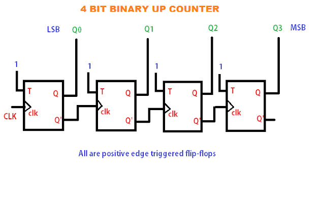
4 BIT up Counter and BCD Using Discrete Transistor

Counters | CircuitVerse

Counter Unit

Solved 1) Draw a block diagram to illustrate the interface | Chegg.com

Dual n-bit Gray code counter block diagram-style #2 | Download

Digital Frequency Meter : Construction, Working and Its Applications

RF Frequency Counter | Microwave Frequency Counter

Timer Counter Block Diagram - BINARYUPDATES.COM