3 Wire Control Circuit Ladder Diagram
Ladder diagram start stop plc logic wire control program conditional Circuit reverse starter basic schematic diagrams insinkerator plc dol electricala2z rotary direct Logic delay plc traffic relay reverse timer circuit mitsubishi diagrams induction siemens operations mikrora pilot dummies schematic programmable controllers timed
3 Wire Start Stop Ladder Diagram
3 wire start stop ladder diagram Control of traffic light ladder logic diagram Logic wiring hvac plc elevator
Ladder diagrams
Allen bradley vfd powerflex 4m- 3 wire control operation3 wire start stop ladder diagram Wire motor control diagram circuit ladder basicsWire control vfd motor diagram powerflex 4m bradley allen basics operation ladder circuit.
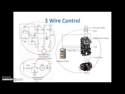
Ladder plc logic motor phase control diagram stop start programming using wire circuit siemens system three stepper instrumentationtools arduino electrical3 wire motor control circuit Ladder diagram basics #3 (2 wire & 3 wire motor control circuit).

Allen Bradley VFD Powerflex 4M- 3 Wire Control Operation | FunnyDog.TV

Ladder Diagram Basics #3 (2 Wire & 3 Wire Motor Control Circuit) - YouTube

Ladder Diagrams - RoboticsUp

3 Wire Motor Control Circuit

3 Wire Start Stop Ladder Diagram

Control Of Traffic Light Ladder Logic Diagram